Views: 0 Author: Site Editor Publish Time: 2026-09-14 Origin: Site
What happens when gravity clarification cannot remove fats, oils, grease, and suspended solids effectively? Poor separation can increase discharge costs and make wastewater treatment unstable.
Dissolved air flotation uses microscopic air bubbles to lift contaminants to the water surface for removal. It is especially effective for light, slow-settling, and emulsified materials.
In this article, you will learn how DAF systems work, what contaminants they remove, and how to select a system based on flow rate, wastewater characteristics, and treatment targets.
Dissolved air flotation relies on the generation of 30-50 micron microbubbles that attach to flocculated particles, forcing the rapid surface separation of TSS, FOG, and insoluble BOD/COD.
Selecting the correct Air Flotation Machine requires precise matching of hydraulic loading rates, the Air-to-Solids (A/S) ratio, and solids loading capacities to the facility’s unique wastewater characterization.
Successful implementation demands rigorous pilot testing, accurate jar testing for chemical dosing, proper flocculation chamber design, and the mandatory integration of upstream screening and equalization.
Table of Contents
A comprehensive wastewater characterization study must precede any equipment selection. Designing a treatment system based on assumed flow rates or generic contaminant profiles guarantees operational failure. Engineers must measure peak hydraulic flows, temperature variations, pH swings, and specific contaminant loads over a representative production cycle. You cannot rely on a single grab sample. Instead, pull flow-proportional composite samples over a 24-hour period to capture the true variability of the plant discharge. This baseline data dictates the physical sizing and chemical requirements of the separation equipment.
The primary targets for this separation technology include TSS, FOG, insoluble Biological Oxygen Demand (BOD), Chemical Oxygen Demand (COD), and precipitated heavy metals. Understand that this physical separation process only removes insoluble contaminants. Soluble BOD and COD require downstream biological treatment. By removing the bulk of the insoluble load upfront, facilities protect downstream biological systems from organic overloading and toxic shock.
Specific industries present unique wastewater challenges where this technology excels. We see distinct operational profiles across different manufacturing sectors:
Meat and Poultry Processing: High concentrations of blood, fats, and proteins create heavy FOG and BOD loads. The system easily floats these buoyant organic materials, preventing them from blinding downstream aeration basins.
Pulp and Paper: Wastewater contains high volumes of fibrous solids. The microbubbles effectively lift these fibers, preventing them from settling and putrefying in holding tanks. Recovered fibers can sometimes be repurposed.
Petrochemical Refining: Emulsified oils and hydrocarbons require precise chemical charge neutralization followed by aggressive air flotation to meet strict discharge permits.
Dairy Processing: Milk fats and suspended proteins form tight emulsions. Proper coagulation breaks these emulsions, allowing the air bubbles to strip the fats out of the water column.
Municipalities enforce strict surcharge thresholds for industrial discharges. Facilities exceeding baseline limits for TSS and FOG face exponential fee increases based on the total mass of contaminants released. Mapping these local municipal surcharge thresholds directly to the required effluent quality establishes the performance baseline for the treatment system. If your local publicly owned treatment works limits FOG to 100 mg/L, your system must consistently output effluent below 80 mg/L to maintain a safety margin.
Establishing the return on investment framework requires calculating the payback period based on the reduction of these surcharges. Compare the projected monthly savings in municipal fees against the operational costs of the treatment system. These operational costs include electricity for the pumps, chemical consumables like polymers and coagulants, and sludge disposal fees. In many high-load food processing applications, eliminating FOG surcharges yields a rapid payback period. You must also factor in the reduced maintenance costs on downstream sewer lines, which no longer suffer from heavy grease blockages.
The core physics of the system rely on the whitewater recirculation loop. A portion of the clarified effluent is drawn from the discharge end of the unit and pressurized by a recycle pump. Compressed air is injected into this pressurized stream. According to Henry's Law, the higher the pressure, the more air dissolves into the liquid. This creates a fully saturated, pressurized liquid stream operating typically between 60 and 90 PSI.
This saturated stream travels to the contact zone at the front of the unit. Here, it passes through a pressure release valve or specialized injection nozzles. As the pressure drops rapidly to atmospheric levels, the dissolved air comes out of solution. This phase change forms a dense cloud of 30-50 micron microbubbles. These bubbles are small enough to avoid creating turbulent currents but numerous enough to provide massive surface area. They look like white milk entering the tank.
The Air-to-Solids (A/S) ratio dictates system success. This ratio calculates the precise mass of air required to float a specific mass of incoming solids. If the A/S ratio is too low, heavy flocs will sink. This contaminates the effluent and overloads the bottom auger. If the A/S ratio is too high, the system wastes electrical energy compressing unnecessary air. Engineers must calculate this ratio based on the peak solids loading rate determined during the characterization study.
Chemical pretreatment is a mandatory prerequisite for maximizing separation efficiency. Wastewater contaminants often carry negative surface charges, causing them to repel each other and remain in suspension. Coagulants such as aluminum sulfate or ferric chloride are injected to neutralize these charges. This allows particles to collide and form micro-flocs. Flocculants, typically long-chain polyacrylamides, are then added to bind these micro-flocs into larger, structurally stable macro-flocs.
The environment where this chemical reaction occurs heavily influences the outcome. We evaluate two primary flocculation designs based on plant layout and flow variability.
Flocculator Type | Design Mechanics | Operational Advantages | Field Limitations |
|---|---|---|---|
Continuous Stirred-Tank Reactors (CSTR) | Open tanks utilizing variable-speed mechanical mixers to blend chemicals. | Highly forgiving of sudden flow variations. Provides excellent, adjustable retention time. | Requires a significantly larger physical footprint and consumes more electrical power. |
Serpentine Pipe Flocculators | Plug-flow design through a series of PVC or stainless steel pipes with static mixers. | Extremely compact footprint. Delivers highly controlled mixing energy without moving parts. | Requires consistent feed pump pressure. Susceptible to clogging if large debris enters the pipe. |
Once the macro-flocs enter the contact zone, the physical interaction with the microbubbles begins. The bubbles nucleate directly onto the polymer chains or become trapped within the floc structure. This drastically reduces the bulk density of the particle matrix, forcing it to rise rapidly to the surface.
As the buoyant particle matrix rises, it forms a thick surface sludge blanket known as the float. This blanket continues to thicken as water drains out of it and back into the main vessel. Maintaining the structural integrity of this float is essential. Excessive turbulence in the tank will cause the float to break apart and resuspend solids into the clarified water. Operators must monitor the float thickness visually or via sensors to ensure it does not become too heavy and sink.
Mechanical skimming mechanisms remove the float. A chain-and-flight skimmer slowly drags specialized blades across the surface. These blades pull the sludge up an inclined beach and into a collection hopper. Simultaneously, a bottom auger system captures heavy, settled solids like grit or un-flocculated dirt that failed to float. This dual-removal mechanism ensures the continuous operation of the Air Flotation Machine without requiring manual cleanouts. The skimmer blades are typically made of neoprene or UHMW polyethylene to maintain a tight seal against the beach incline.
Equipment geometry dictates hydraulic flow dynamics and facility integration. Rectangular units are the standard for most industrial applications. They utilize a cross-flow design where water enters one end and exits the other. This geometry supports modular expansion, fits easily into standard building layouts, and provides highly predictable plug-flow hydraulics. You can easily align multiple rectangular units side-by-side to scale up treatment capacity as production grows.
Circular units operate on radial flow dynamics. Water enters the center and flows outward toward the perimeter. These units are typically reserved for massive hydraulic flows, often exceeding several thousand gallons per minute. They are common in large municipal wastewater plants or massive pulp and paper mills. In these environments, constructing a concrete circular basin is more practical than fabricating massive steel rectangular tanks. The skimming mechanism on a circular unit rotates around a center pivot, sweeping the sludge into a radial trough.
The distinction between standard and high-rate systems comes down to surface loading rates and retention times. Standard-rate systems utilize open tanks with retention times ranging from 20 to 30 minutes. They have lower surface loading rates, meaning they process less water per square foot of surface area. This makes them highly resilient to shock loads and chemical dosing errors. If your chemical feed pump loses prime for two minutes, a standard-rate tank has enough buffer volume to prevent a total loss of effluent quality.
High-rate systems utilize lamella plates packed into the separation zone. These inclined tubes or plates drastically increase the effective settling and floating area within the same physical footprint. High-rate systems can process double or triple the hydraulic load of a standard unit of the same size. However, the tight spacing of the lamella plates makes them susceptible to blinding. If the chemical flocculation fails and sticky FOG coats the plates, operators must shut down the system and manually pressure-wash the plate packs.
Environmental and safety compliance dictates the choice between open and closed-top systems. Standard industrial applications utilize open-top tanks for easy visual inspection and maintenance access. Operators can easily see the float blanket and adjust skimmer speeds accordingly. However, specific wastewater streams require vapor-tight containment to protect workers and the surrounding environment.
Closed systems are specified when dealing with Volatile Organic Compounds (VOCs), severe odor control requirements, or hazardous environments. In petrochemical refineries, the wastewater often contains explosive hydrocarbon vapors. These applications require a fully sealed unit with nitrogen blanketing. Explosion-proof electrical components are mandatory to prevent catastrophic ignition. The sealed roof also connects to vapor recovery units or thermal oxidizers to safely destroy the off-gassed compounds.
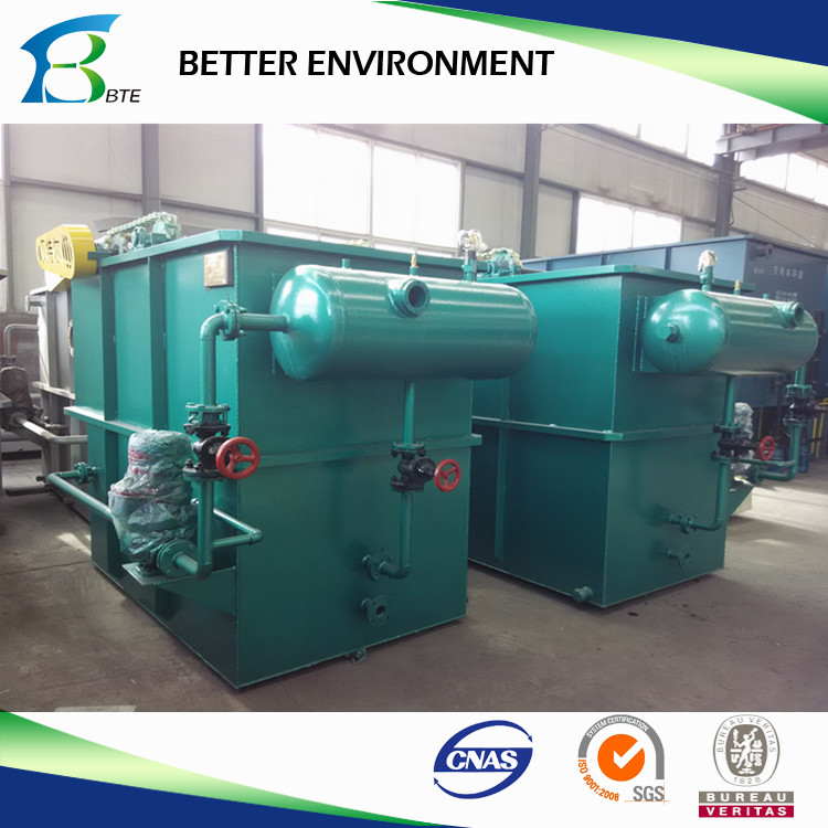
The whitewater generation system is the mechanical heart of the process. Traditional configurations utilize an external air compressor, a large saturation tube, and a standard centrifugal recycle pump. While reliable, this setup requires maintaining three separate pieces of rotating equipment. It consumes significant electrical energy and requires constant tuning of the air rotameter to prevent large, turbulent bubbles from forming in the saturation vessel.
Modern designs utilize multiphase pump systems, often employing regenerative turbine technology. These specialized pumps draw in atmospheric air and clarified effluent simultaneously. They shear the air into the liquid directly within the pump casing. This eliminates the need for an external air compressor and a bulky saturation vessel. Multiphase pumps provide highly consistent bubble sizes and reduce overall energy draw. They significantly lower long-term maintenance requirements by reducing the number of moving parts on the skid.
Sludge management dictates a significant portion of operational expenses. The design of the surface skimmer directly impacts the percentage of dry solids in the removed sludge. Counter-current skimming moves the blades in the opposite direction of the water flow. This pushes the sludge blanket together, allowing more water to drain out before removal. The result is a thicker, drier sludge that reduces hauling costs.
Co-current skimming moves the blades in the same direction as the water flow. This removes the sludge faster and handles massive solids loading better, but typically results in a wetter sludge. Integrating variable speed drives on the skimmer motor allows operators to adjust the skimming rate based on real-time solids loading. A properly designed beach incline further aids in water drainage. The angle of the beach must be steep enough to allow water to run back into the tank, but shallow enough that the sludge does not roll back over the skimmer blades.
Routine maintenance access prevents catastrophic downtime. The whitewater injection nozzles located in the contact zone are prone to clogging from mineral scaling or rogue debris. Evaluating the ease of access to these nozzles is a primary engineering concern. Operators must be able to isolate and clear a clogged nozzle without draining the entire tank. Look for systems featuring external nozzle headers with individual isolation valves.
For applications with heavy FOG or high mineral hardness, integrating Clean-in-Place (CIP) systems is highly recommended. CIP systems automate the injection of hot water and caustic solutions through the internal piping and nozzles during scheduled downtime. This removes grease buildup and mineral scaling. It restores optimal hydraulic flow without requiring confined space entry or manual scrubbing.
Material selection dictates the operational lifespan of the equipment. Matching the metallurgy to the specific wastewater chemistry prevents rapid corrosion and structural failure. You must analyze the chloride levels, pH extremes, and operating temperatures before approving fabrication drawings.
Material | Primary Application | Corrosion Resistance | Operational Lifespan Considerations |
|---|---|---|---|
Coated Carbon Steel | Neutral pH, low chloride industrial wastewater. | Low to Moderate. Relies entirely on the integrity of the epoxy coating. | Requires regular inspection. Any scratch in the coating leads to rapid localized rusting and structural degradation. |
304 Stainless Steel | Standard food processing, municipal, and general manufacturing. | High. Excellent resistance to standard organic acids and mild cleaning chemicals. | Industry standard. Provides decades of reliable service in non-chloride environments. |
316 Stainless Steel | High chloride environments, harsh chemical processing. | Very High. Resists pitting from chlorides and aggressive sanitizers. | Necessary for coastal facilities or plants using heavy brine solutions. |
Duplex Stainless Steel | Extreme petrochemical, high temperature, highly corrosive streams. | Extreme. Superior strength and resistance to stress corrosion cracking. | Used only when standard stainless steels fail. Offers maximum longevity under severe stress. |
Facility layout often forces compromises between equipment size and operational flexibility. Ultra-compact, high-rate systems save valuable floor space. However, they demand highly precise chemical dosing and strict flow control. Because the retention time is short, any failure in the flocculation process immediately results in solids washing out into the clean effluent stream. You must have highly trained operators to manage these tight tolerances.
Standard-rate systems consume significantly more floor space but offer operational forgiveness. The larger tank volume acts as a buffer. If a chemical dosing pump temporarily loses prime, or if a sudden spike in TSS enters the system, the longer retention time allows the system to absorb the shock without immediately violating discharge permits. Facilities with limited automation or highly variable production schedules should prioritize standard-rate designs to minimize compliance risks.
Chemical consumption represents a major ongoing operational expense. Facilities must balance the initial capital expenditure (CapEx) of advanced dosing controls against the long-term operational expenditure (OpEx) of chemical waste.
Manual chemical dosing relies on operators adjusting pump speeds based on visual observation. This invariably leads to over-dosing to play it safe. Over-dosing results in wasted chemicals and artificially inflated sludge volumes. Investing higher CapEx in automated dosing systems ensures precise chemical application. Utilizing inline pH, ORP, and TSS sensors tied to variable frequency drive dosing pumps matches the chemical feed directly to the real-time contaminant load. This automation drastically reduces monthly chemical OpEx and minimizes the volume of sludge requiring disposal.
Blinding the system or damaging mechanical components with large solids is a frequent point of failure. Wastewater often contains rags, plastic debris, or large organic chunks that can foul the recycle pump or jam the bottom auger.
Mandate the installation of upstream rotary screens. A 1mm to 2mm screen effectively removes gross solids before they reach the treatment system. Furthermore, installing an equalization tank after the screen normalizes the flow rate and homogenizes the pH and temperature. This provides a stable baseline for chemical treatment and prevents sudden shock loads from overwhelming the separation zone.
Sudden surges in wastewater flow that exceed the design capacity cause extreme turbulence within the vessel. This hydraulic overloading breaks apart fragile flocs and carries suspended solids directly into the clean effluent weir, a phenomenon known as short-circuiting.
Properly size the upstream equalization tank to absorb peak production flows. Utilize feed pumps equipped with variable frequency drives, controlled by a level sensor in the equalization tank. This ensures a steady, controlled hydraulic loading rate into the separation unit, regardless of upstream production spikes.
Over-dosing or under-dosing coagulants and flocculants destroys separation efficiency. Under-dosing results in pin floc, which are tiny particles that fail to float. Over-dosing wastes money, creates a sticky sludge that blinds lamella plates, and can actually reverse the particle charge, causing them to repel each other again.
Implement rigorous, continuous jar testing protocols to verify chemical dosages against real-world wastewater samples. Install automated pH and ORP sensors to adjust coagulant feed rates dynamically. This ensures the chemistry matches the real-time contaminant load and prevents operator guesswork from ruining the effluent quality.
Inadequate infrastructure to handle the volume of floated sludge causes severe system backups. The skimmer continuously removes sludge, which typically contains only 3% to 10% dry solids. If the receiving hopper or holding tank fills up, the skimmer must be shut down. This causes the float blanket to collapse and sink back into the water column.
Design adequate sludge holding tanks equipped with decanting valves to remove separated water. Evaluate and specify secondary dewatering equipment, such as filter presses or decanter centrifuges, during the initial system specification phase. This ensures the facility can efficiently process and dispose of the generated sludge volume without interrupting the primary separation process.
Initiate a formal, multi-day wastewater characterization study to capture peak flow rates and maximum contaminant concentrations.
Perform initial jar testing with a qualified chemical vendor to determine the exact coagulant and flocculant requirements for your specific wastewater matrix.
Request pilot-scale unit trials from shortlisted manufacturers to validate performance guarantees and observe the system's resilience to your facility's unique operational fluctuations.
Audit your existing upstream infrastructure to ensure adequate screening and equalization capacity exists before installing new separation equipment.
Evaluate secondary sludge dewatering technologies to handle the projected volume of floated solids generated by the new system.
A: Dissolved air flotation uses high pressure to dissolve air into water, releasing it as 30-50 micron microbubbles when pressure drops. Induced air flotation uses mechanical agitation or gas injection to create much larger bubbles, often over 100 microns. The high-pressure method is superior for fine suspended solids and emulsified oils, while induced air is typically used for heavy, bulk oil recovery in petroleum applications.
A: Effective systems require microbubbles ranging from 30 to 50 microns in diameter. Bubbles in this size range have a slow rise velocity, preventing turbulence in the tank. They provide massive surface area, allowing them to easily nucleate onto or become entrapped within the chemical floc structure for optimal lifting power.
A: The ratio determines if enough air mass is available to lift the incoming solids mass. A low ratio causes heavy flocs to sink, contaminating the effluent. A high ratio wastes electrical energy by compressing unnecessary air. It must be precisely calculated based on peak solids loading to ensure efficient separation without excessive power draw.
A: Most wastewater contaminants carry negative surface charges, causing them to repel each other and stay suspended. Chemical pretreatment uses coagulants to neutralize these charges and flocculants to bind the particles into larger masses. Without this chemistry, microbubbles cannot effectively attach to the microscopic, repelling contaminants.
A: Yes, but only if the metals are first precipitated out of solution. Dissolved heavy metals must be subjected to specific pH adjustments and chemical precipitation to convert them into insoluble solid particles. Once converted into suspended solids, the system can effectively flocculate and float them to the surface for removal.
A: Standard-rate systems typically require a hydraulic retention time of 20 to 30 minutes. This duration allows the microbubbles sufficient time to attach to the flocs and gently lift them to the surface. It prevents disruptive turbulent currents that could break the sludge blanket apart and degrade effluent quality.